Integrity has large experienced in managing both conventional bore hole site investigations and small scale engineering seismic surveys.
We have provided foundation design data for projects as diverse as housing estates and hydro-electric schemes. We have proven track record in determining the condition of shallow (< 10 m.) brick and concrete drains and determination of water filled altered zones 200 m ahead of hard rock tunnel drives to and accuracy of 5 m. and better.
|
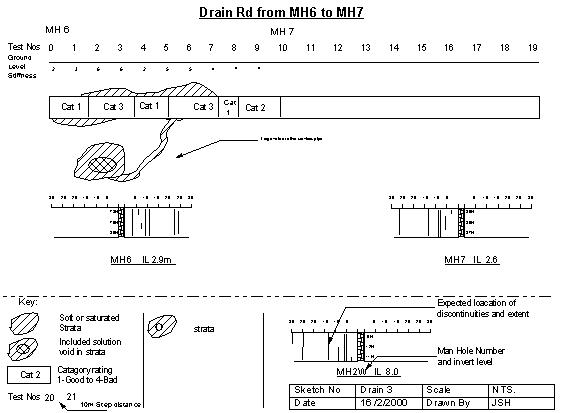
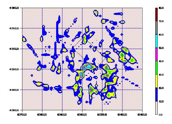
This is a typical analysis from our shallow seismic survey. Not only have we determined the condition of the sub-strata but also the condition of the drain fabric. There was a large amount of hand analysis but now we are automating the process to remove the gut feeling of pure guess work interpretation. An automated plot of the same section is given below. |
 |
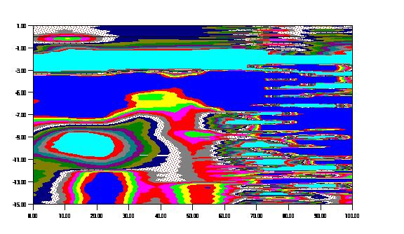 |
The survey stopped at 60m. The light blue areas are the voids, the
left to right light blue patch is the drain we are testing.
The blue eye below is another drain , abandoned as we found out later. The narrowing of the dark blue band and contour color change would correspond to a connection from the upper drain to the lower one. The corrected depth profile is based on a soil stiffness determination of the instiu seismic velocity rather than the traditional acoustic resistance methods. |
 |
Looking for rock ahead of the tunnel
drive in Sri Lanka.
A simple drop weight gave adequate energy to detect rock formations some 300 to 400 metres below ground. Typically if you perform a refraction seismic survey the resolution is the number of shot points per line, having 100's of geophones doesn't improve the accuracy. |
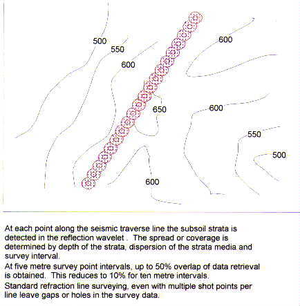 |
The survey resolves a soil or strata column formed by the loci of the impacter and the seismic transducer. By surveying in a grid pattern 3-D seismic surveys can be produced similar to the one below |
 |
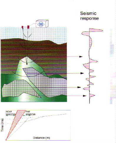 |
Straight down and straight up! Basically the optimum window methods still only yield a single point, as the seismic records have to be resolved into a single reflection point. |
| A fairly standard seismic refraction diagram, with all the transducers you still only resolve a single point. | 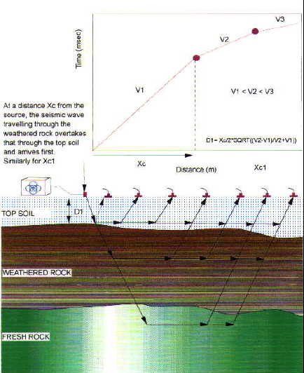 |
| Radar, we have done it both in buildings on roads for services and plain geophysical profiling. Well it works but you have to remember the basic physics behind the method of evaluation, surveying. We used a simple seismic survey as back up in fact the seismic survey was faster and more accurate on the rock head detection. We found the older analogue equipment was better than the "new" digital systems. Generally in the geophysical industry the front end electronics in the equipment is not as good as it was. | 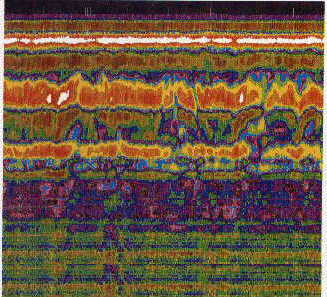 |
| Our tunnel experience is wide spread typically the results end up in a sketch of a tunnel slab profile. Though the sketch is simple the working to wards the sketch is hard but achievable. |
 |